
I. Overview
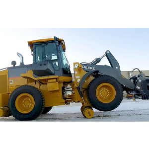
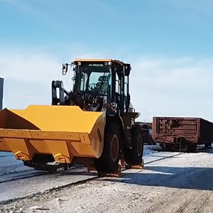
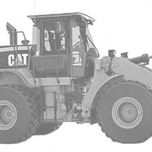
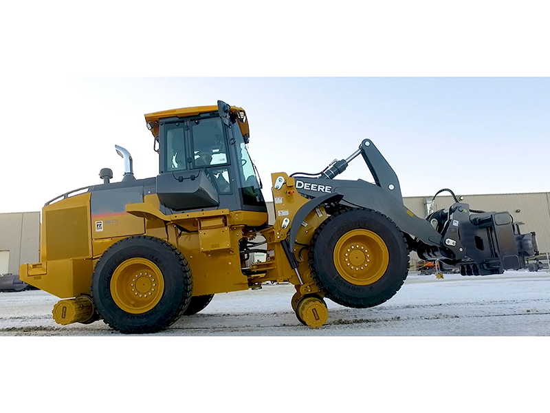
Loaders are widely used in bulk material logistics both at home and abroad. Our company has made adaptive modifications to the loaders based on the demands of railway logistics yards. While retaining the basic functions of the loaders, we have further expanded their capabilities, enabling them to effectively perform railway traction operations. They are suitable for large, medium and small-sized logistics, grain and other dedicated lines in China.
The adaptive modification of loaders mainly includes parts such as rail guidance devices, coupler traction devices, air-filled braking devices, hydraulic system modification, attachment quick-change devices and counterweights.
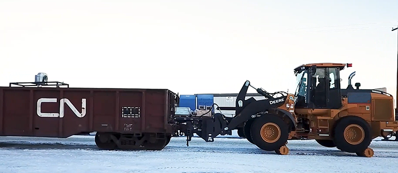
The coupler traction device can be adapted to the owner's existing loader, safely pulling railway vehicles without affecting their original vehicle functions. Specialized equipment that enables it to not only travel on railway tracks and pull rail vehicles for operations, but also move and transfer on ordinary roads and perform daily tasks.
It can effectively solve the problem of inconvenient use of locomotives on large, medium and small-sized dedicated lines in railway logistics yards, large mining enterprises, etc., reduce costs and increase efficiency, and promote the development of enterprises.
Product advantages
1. In coordination with the owner's existing loader equipment for technological transformation, we will maximize the efficiency of the equipment and improve its utilization rate without affecting the original vehicle functions.
2. Low operating costs
The equipment is easy to operate and does not require a special operation certificate. The loader driver can operate it with a little effort.
No special maintenance is required. Daily maintenance by the loader maintenance personnel is sufficient.
It is convenient for maintenance. Maintenance personnel of the loader can carry out vehicle maintenance and major overhauls without the need for special maintenance personnel, and the maintenance cost is low.
The market stock of major components is large, the procurement cycle is short, and the cost of accessories is low.
In large, medium and small freight yards, it can replace locomotive operations and reduce operating costs.
3. High security
It has replaced the original methods such as hanging Angle irons and forklift pushing, greatly reducing the risks of safety accidents such as derailment, wire rope breakage and damage to the vehicle compartment.
4. High efficiency
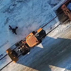
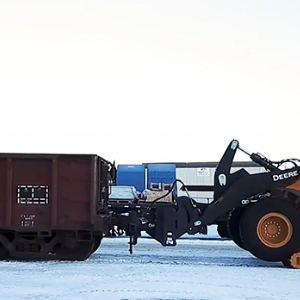
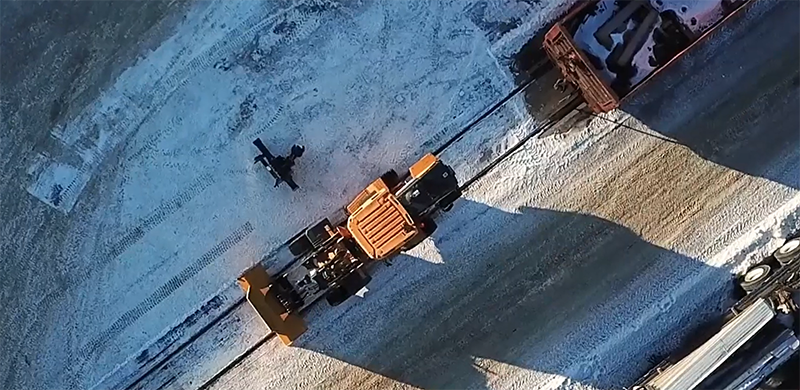
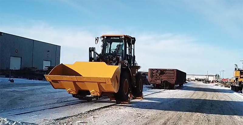
It can be operated by both road and railway. It can be flexibly and quickly transferred to the designated location via road. After connecting the coupler, the vehicle can be moved.
5. It has good functional expansion
It can be equipped with various attachments to achieve multi-functional use of the vehicle, such as forks, sweeping devices, snow removal devices, etc.
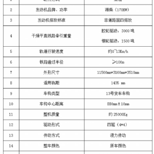
2.2 Technical Parameters
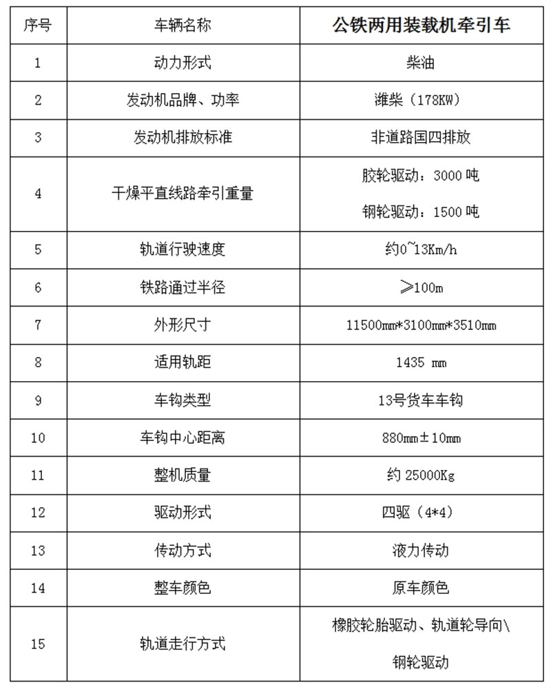
2.3 Technical Description
Product adaptability modification mainly includes parts such as rail guidance devices, coupler traction devices, air-filled braking devices, hydraulic system modification, and quick-change devices for attachments.
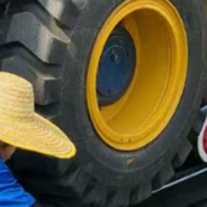
1. Rail guidance device
The vehicle track drive running adopts the original loader drive system. The rubber drive wheels are pressed onto the track after adjusting the offset distance. The rubber drive wheels are closely attached to the track, and the track wheels, as passive wheels, are in close contact with the track to ensure that the vehicle always runs along the track. The forward and backward movement of the vehicle is controlled by the original vehicle's gear shifting mechanism.
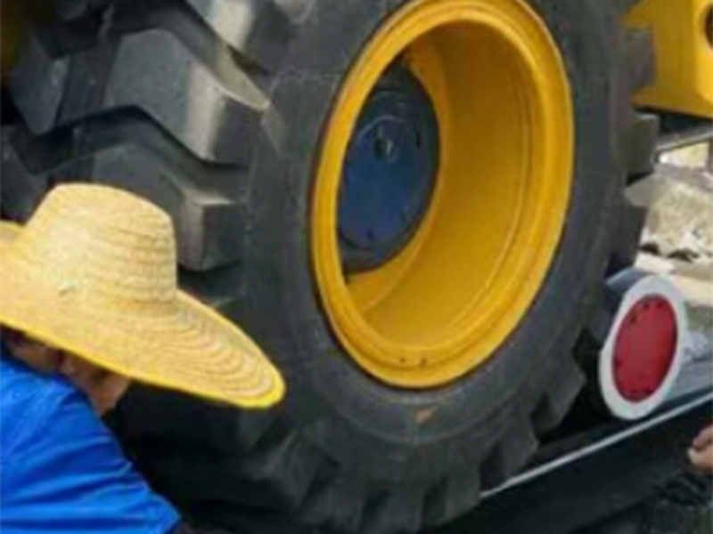
Schematic diagram of the drive wheel and track wheel layout
1.1 The track and the road surface share one power system. When operating on the road surface, the steel wheels are in the lifted position, which does not affect the vehicle's drive and steering. When performing track running operations, the steel wheels fall onto the track, and the driving rubber wheels are in close contact with the friction driving surface on the steel wheels. During the running process, the driving rubber wheels push the steel wheels to move on the track.
The steel wheels can be lifted and lowered through a hydraulic device, achieving the conversion between road and rail transportation. The front steel wheels are fixedly connected to the landing gear, while the rear steel wheels are connected to the landing gear through pins, allowing for appropriate swaying to ensure that both sets of steel wheels are always in contact with the track.
After the steel wheel is raised, a fixed pin is set to prevent it from accidentally falling due to long-term inactivity or malfunction, which may affect driving safety.
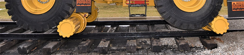
Schematic diagram of steel wheel drive layout
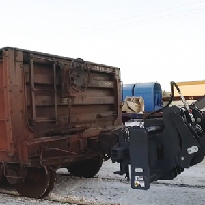
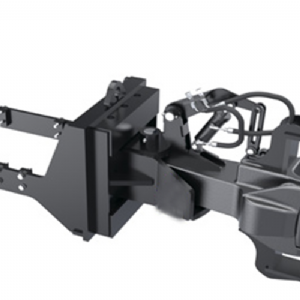
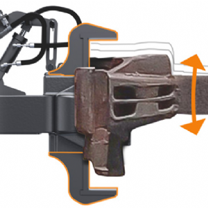
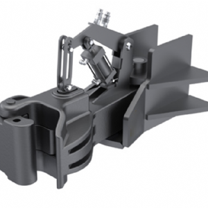
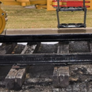
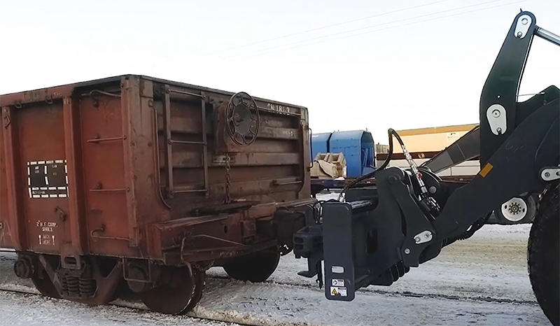
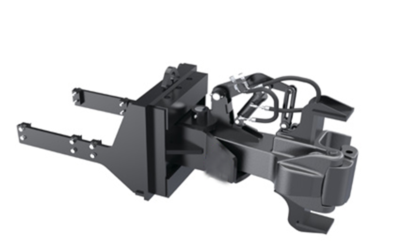
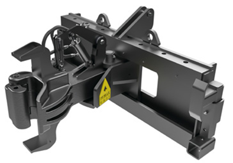
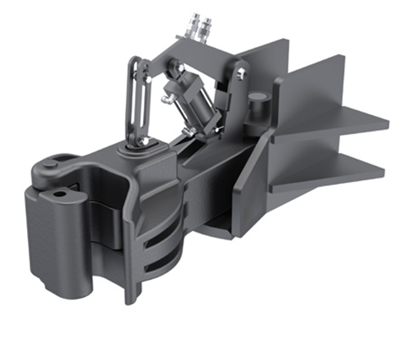
2. Coupler traction device
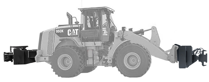
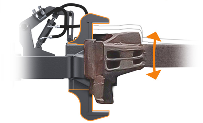
Two 13# special couplings for train freight cars are respectively configured at the front and rear ends of the vehicle, which are used for the connection of freight trains to achieve bidirectional traction of the tractor. The coupler is equipped with a lifting function, facilitating the connection and disengagement of vehicles.
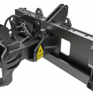
Schematic diagram of the front and rear traction couplings
The rear coupler coupler mounting seat is connected to the loader body, and the coupler is installed on the coupler mounting seat. The height of the coupler is 880mm±10mm, and the height of the coupler is not adjustable.
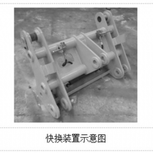
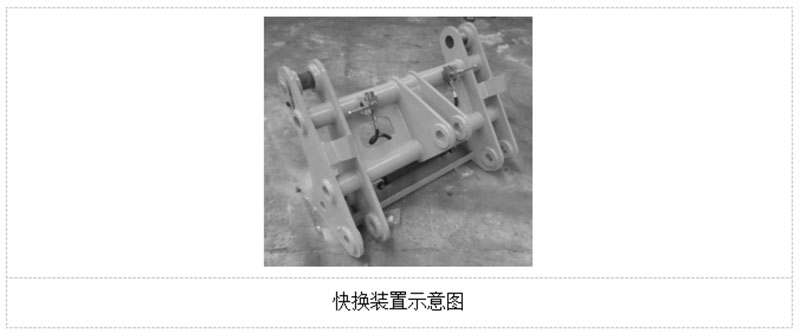
The front coupler mounting seat is a separate structure. It is installed on the loader through a quick-change device installed on the loader's large arm. The height of the coupler can be adjusted as needed.
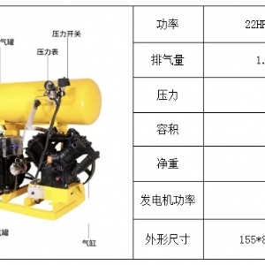
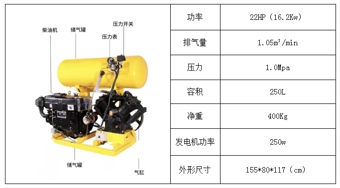
3. Air-filled braking device
The air-filled braking device consists of a gas-making device, a gas-storage device, a control device, a safety device and pipelines and pipe fittings, etc.
The air supply device serves as the air source for the air-filled braking system, providing compressed air for the braking relief of the train. The gas-making device is powered by a diesel engine, which drives the air compressor to produce compressed air. The compressed air is temporarily stored in the air storage tank, saving the time for the train to ease.
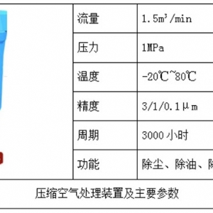
The control device is an important component of train braking, consisting of three parts: the compressed air handling device, the pressure regulating device, and the braking relief control device.
The compressed air treatment device mainly conducts triple treatment of dust removal, oil removal and water removal on the compressed air discharged from the gas-making device to obtain dry compressed air.
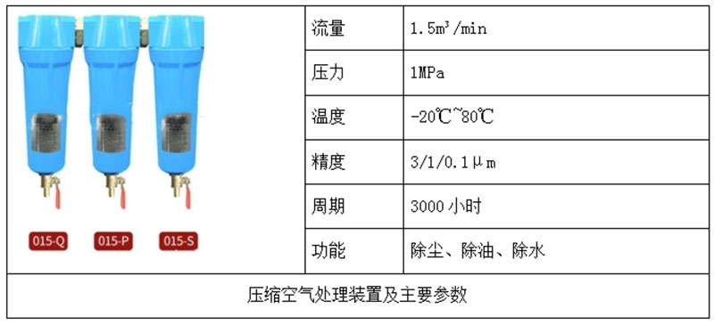
The pressure regulating device is used to adjust the exhaust pressure of the gas storage device to adapt to train braking and relief. The pressure adjustment range is 0 to 1MPa, with no level adjustment. It is applicable to the pressure relief of 0.55MPa or 0.65MPa for the train.
The control device is the part that controls the braking and relief of the train. By controlling the on-off and connection routes of the air lines, it realizes the braking and relief of the train.
4 Hydraulic System
The hydraulic system mainly includes the vehicle steering system, the boom working system and the rail conversion system. The overall hydraulic system is mainly based on the original vehicle's hydraulic system, adhering to the fundamental concept of maintaining the original hydraulic system's functions. New functions are achieved by adding hydraulic valves, control circuits, and other means.
The vehicle's steering system is the original hydraulic system of the vehicle. The basic route remains unchanged. A circuit locking device is installed. When the vehicle is in track mode, the circuit locking device is opened and the vehicle's steering function is locked. When the vehicle is in road mode, the circuit locking device is turned off and the vehicle's steering function is restored.
The large arm working system, as the main hydraulic control device of the original vehicle, adds a hydraulic circuit for the quick-change device to facilitate the hydraulic control of the quick-change device.
6. Painting
The coating of the installation device uses well-known brand engineering paint, which is durable. The surface coating is smooth and flat, without blisters, cracks, wrinkles, missed areas or peeling. The paints of various colors do not stick to each other, and the boundaries are clear. The paint film thickness is 80μm to 120μm, and the adhesion of the paint film is no less than grade 2.
The color of the modified parts is basically consistent with that of the modified vehicle, minimizing color differences. Some components are decorated with other colors.
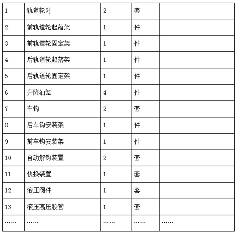
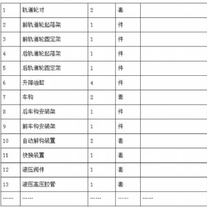
2.3 Main Accessories